


Instrumentation
All stations are equipped with the same instrumentation, manufactured by Guralp Systems Ltd. (Table 1), consisting of: Radian digital broadband velocimeter (in the well, at a depth of approximately 75 m), a Fortis compact broadband accelerometer (on the surface) and a 24-bit digitizer Minimus.
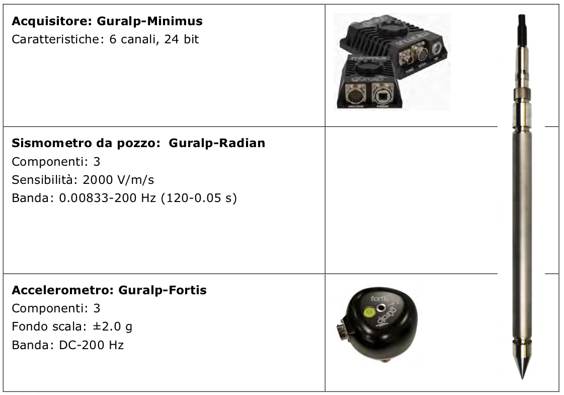
TTable 1 - Models of the main components of the seismological instrumentation in the RSCL stations (produced by Guralp System Ltd.).
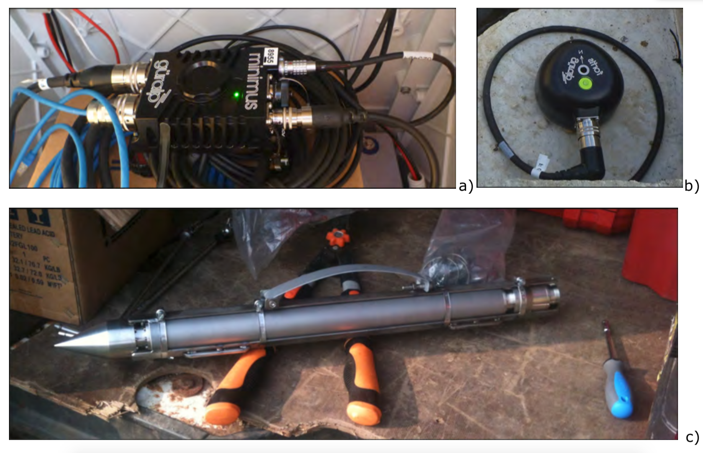
Figure 1 - Testing phase of the instrumentation: a) Guralp Minimus, a 6-channel digital acquisition device; b) Guralp Fortis, an accelerometer for measuring strong ground motion; c) Guralp Radian, a broadband digital well seismometer. In the central part of the seismometer, the spring used to couple the sensor to the well walls can be seen.
The well sensors have been equipped with a coupling system, designed by OGS, which consists of a steel blade tensioned by two flanges integral with the sensor (Figure 1c). The tension of the blade is adjusted so that the sensor, with the addition of a suitable weight, can slide down the pipe. Once at the bottom of the well, the weight is then removed from above. The most delicate phase of the installation was certainly that of lowering the seismometer into the well. The sensor is lowered into the well by means of winches set up in such a way as to allow the cables to enter the well mouth vertically, avoiding friction and rubbing on the metal or concrete (Figure 2). The winches are also used to manage the considerable weight of the instrument which, considering the sensor, the additional grave and the cable, is several tens of kilos.
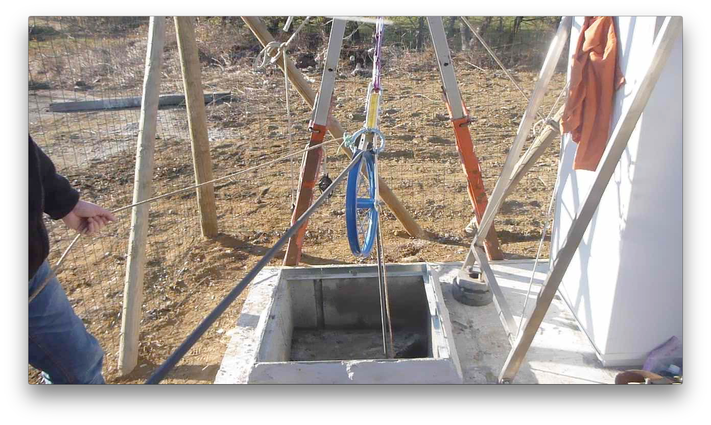
Figure 2 - Insertion phase of the seismometer in the well. Note the winch system used for the signal-cable and for the weight recovery rope to facilitate the descent into the well.
Figure 3 shows an example of a completed station. Note the environmentally friendly fence protecting the site and instrumentation. Finally, Figure 4 shows the interior of a manhole, with the wellhead sealed at the surface and the accelerometer anchored to the concrete pad at the corner. The well is embedded in the concrete platform and is raised about 20 cm above ground level to prevent water from entering in the event of heavy rain. Inside, the wellhead protrudes approximately 50-80 cm above the bottom of the well, again to prevent any accumulation of water from entering the well from the wellhead.
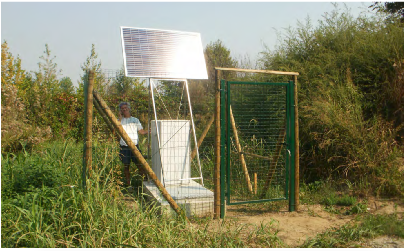
Figure 3 - Example of a completed station. The photograph refers to station OL02. We can recognise: the concrete base; the steel pylon supporting the photovoltaic panel, with, underneath, the cabinet containing all the instrumentation, except for the sensors, and the power supply batteries; in front of the cabinet, the cover of the photovoltaic panel.
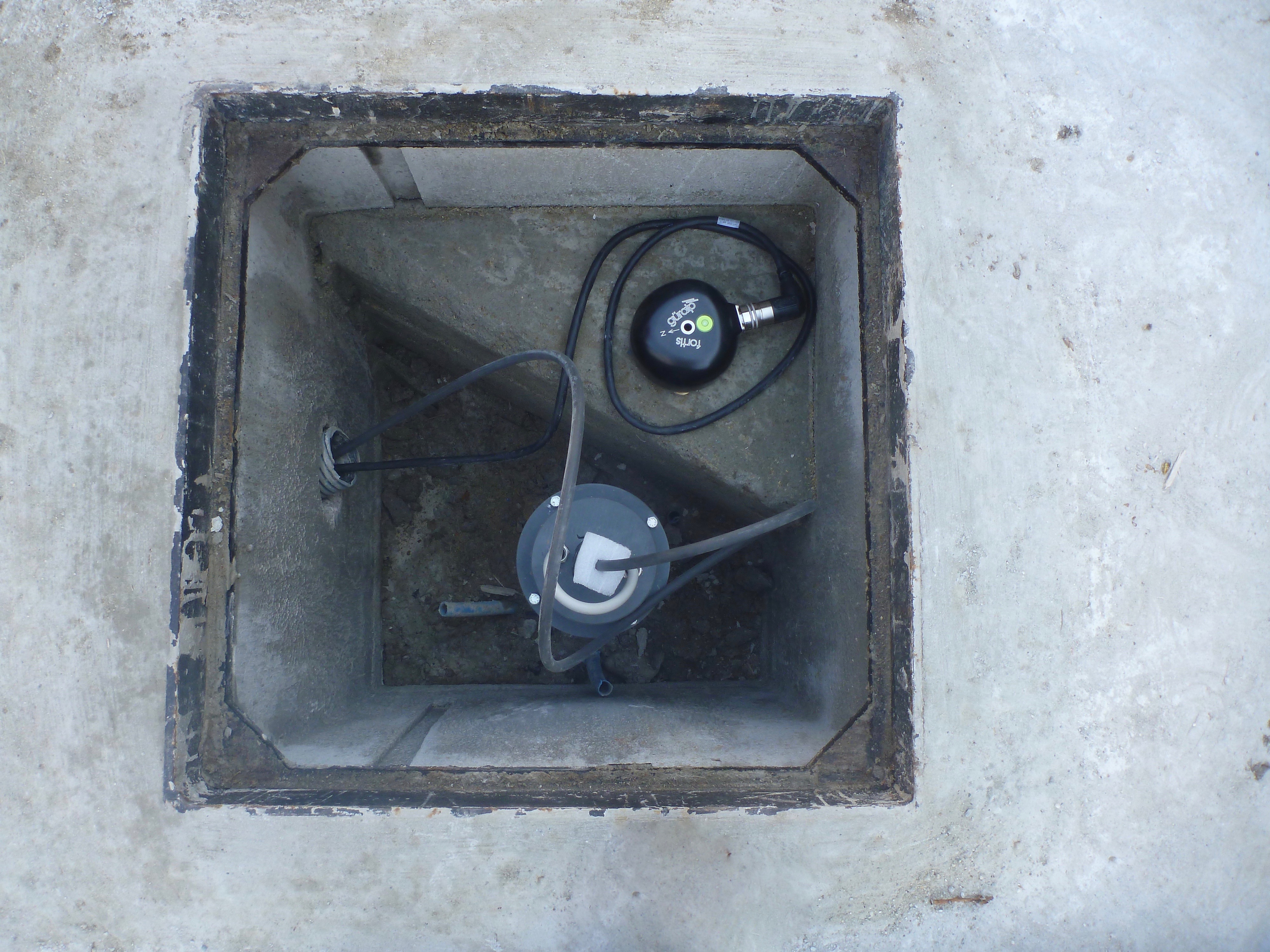
Figure 4 - Example of the inside of a well. The photograph refers to station OL08. In the centre, slightly below, is the capped wellhead from which the seismometer cable exits. At the top right is the triangular base on which the accelerometer is anchored. On the left you can see the entrance to the cable duct which allows the cables to be brought into the cabinet.
Data transmission and storage
All the stations of the Cornegliano Laudense Seismic Network are equipped with a data transmission system supported by the 3G mobile phone network. The data from the stations are sent to the acquisition centre at OGS, allowing also the monitoring of the operating parameters and to carry out maintenance operations when necessary.
Once acquired, the raw data from the monitoring stations are converted to the miniSEED format (international standard for the exchange of digital seismological data) to be processed, analysed and archived in real time on a network storage system with a total capacity of about 20 TB. The RSCL network accumulates approximately 1.2 GB of data per day, so about 0.5 TB per year. The dataset is stored permanently, securely and accessible via web within the infrastructure of the department's central Seismological Research Centre Scientific Section called OASIS. The OASIS web page gives free public access to both the information about the sites and the waveforms recorded continuously by the RSCL, with a one-day latency to allow for any malfunctions or temporary failures in data transmission.
The SeedLinkprotocol is used for real-time data linking and archiving, establishing robust, real-time communication between the acquisition server (RingServer), the stations and the processing and archiving system (BRTT Antelope). The BRTT Antelope performs the real-time processing and analysis functions, which include automatically detecting and locating earthquakes and notifying on-call personnel of any warnings.
Figure 5 shows an image of the seismic control room, located in Sgonico (TS), at the OGS headquarters.
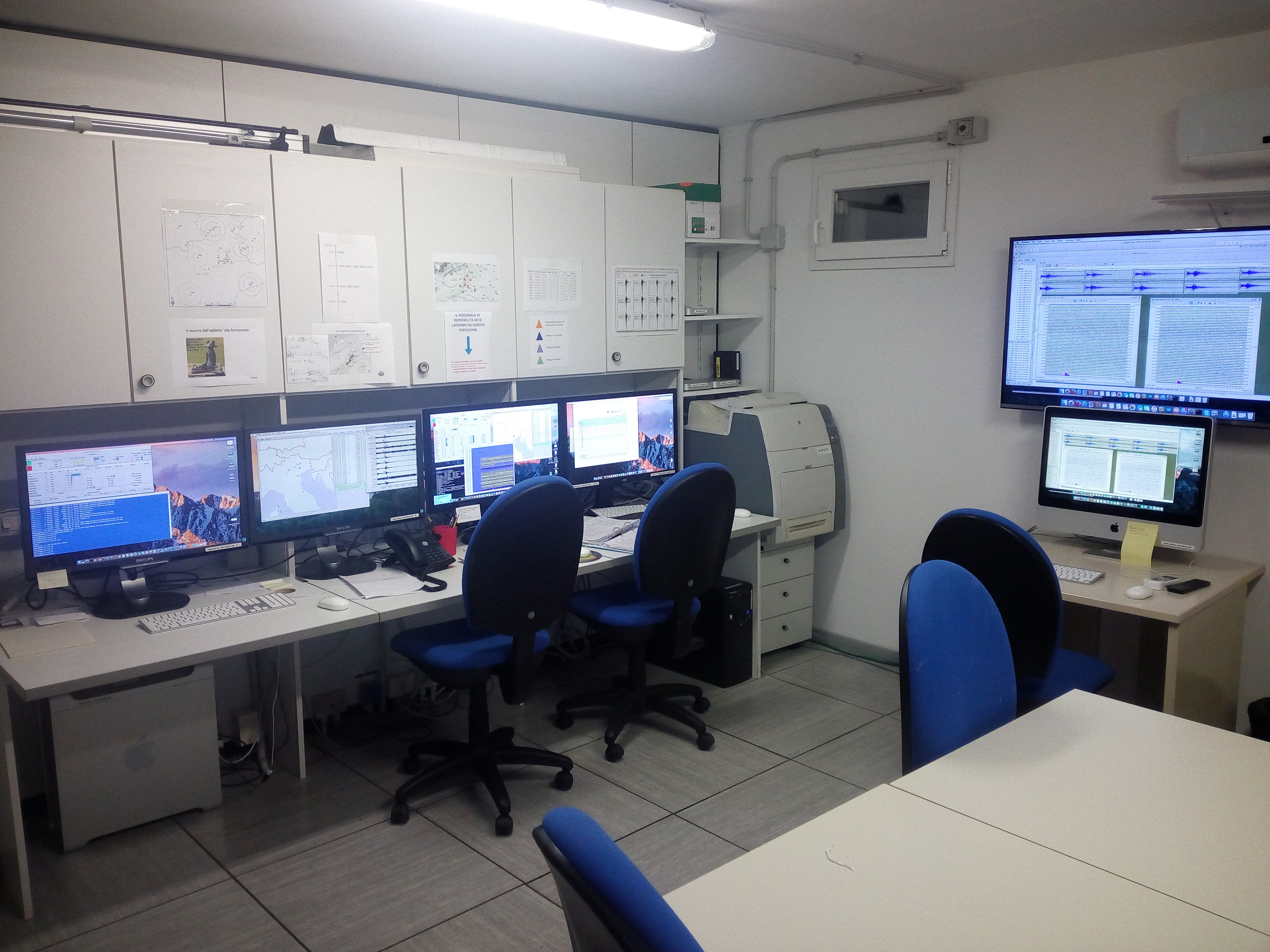
Figure 5 - The monitoring room at the CRS Section premises at the OGS headquarters in Sgonico (Trieste).
For more details, please refer to the "Data and Documentation" section under "Reports".